How to Wire Up a Toggle Switch: A Complete Guide
Learn the fundamentals of toggle switch wiring with step-by-step instructions and safety tips
Safety Warning: Always turn off power at the circuit breaker before working with electrical wiring. If you're not comfortable with electrical work, consult a qualified electrician.
Understanding Toggle Switch Basics
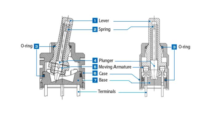
A toggle switch is a simple electrical component that controls the flow of electricity in a circuit. Most common toggle switches have three terminals:
- Common (C): The input terminal where power enters
- Normally Open (NO): Circuit is open when switch is in default position
- Normally Closed (NC): Circuit is closed when switch is in default position
Tools and Materials Needed
Tools Required:
- Wire strippers
- Screwdrivers (flathead and Phillips)
- Voltage tester or multimeter
- Wire nuts or terminal connectors
Materials Needed:
- Toggle switch
- Electrical wire (appropriate gauge)
- Electrical tape
- Wire nuts
Step-by-Step Wiring Instructions
Step 1: Turn Off Power
Locate the appropriate circuit breaker and turn it off. Use a voltage tester to confirm that no power is flowing to the wires you'll be working with.
Step 2: Identify Your Wiring Configuration
Determine whether you're wiring a simple on/off switch or a more complex switching arrangement:
Step 3: Strip Wire Ends
Strip about 3/4 inch of insulation from the ends of your wires using wire strippers. Be careful not to nick the copper conductors.
Step 4: Connect the Common Terminal
Connect the incoming power wire (usually black or hot wire) to the common terminal of the toggle switch. This is typically the center terminal or the one marked "C".
Step 5: Connect the Load Wire
Connect the wire going to your load (light, motor, etc.) to either the NO (Normally Open) or NC (Normally Closed) terminal, depending on your desired switching behavior.
Step 6: Secure All Connections
Ensure all terminal screws are tight and no bare copper is exposed. Wrap connections with electrical tape if necessary for additional protection.
Step 7: Test Your Work
Turn the power back on and test the switch operation. The connected device should turn on/off according to the switch position.
Common Wiring Configurations
Single Pole Single Throw (SPST)

Simple on/off control for one circuit. Most common configuration for basic switching applications.
Single Pole Double Throw (SPDT)
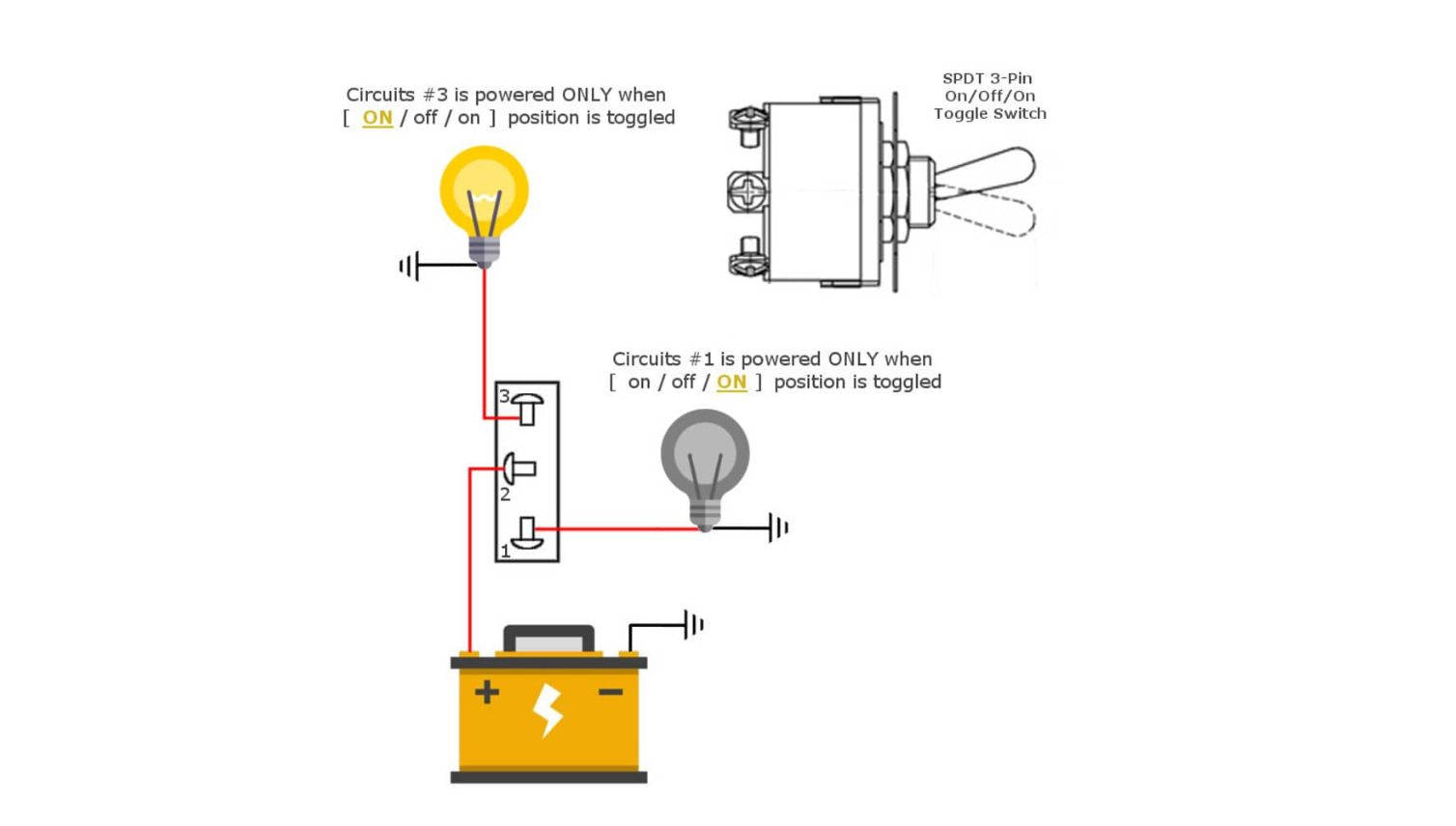
Allows switching between two different circuits or devices from a single input source.
Troubleshooting Common Issues
Switch Doesn't Work
- • Check that power is reaching the switch
- • Verify all connections are tight and secure
- • Test the switch with a multimeter for continuity
Switch Works Backwards
- • You may have connected to NC instead of NO terminal
- • Simply swap the load wire to the opposite terminal
Sparking or Arcing
- • Turn off power immediately
- • Check for loose connections
- • Ensure switch is rated for the load current
Choosing the Right Toggle Switch
When selecting a toggle switch for your project, consider these important factors:
Voltage Rating
Ensure the switch can handle your circuit voltage (120V, 240V, etc.)
Current Rating
Switch must be rated for the maximum current your load will draw
Environmental Rating
Consider moisture, dust, and temperature requirements
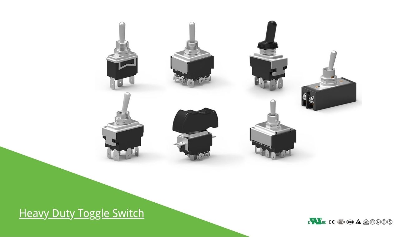
Need Professional Grade Toggle Switches?
Goboll Electronics offers a comprehensive range of certified toggle switches for industrial, marine, and commercial applications. Our switches meet international standards including UL, VDE, TUV, and CE certifications.
Contact Information:
📱 WhatsApp: +86 13285879777
📍 Building 13, Intelligent Industrial Zone No.2777 Ningkang East Road, Yueqing City, Wenzhou City, Zhejiang Province, China